
A programmable thermostat with a color LCD display and touch screen, aesthetically appealing and extremely cost-effective. Complete with a thermometer, pressure gauge, and humidity sensor capable of providing weather forecasts, programmable for daily time slots over the course of a week. In short, a DIY touch screen thermostat.
No, I don’t want to sell it to you, but rather explain how to build it yourself. It consists of a printed circuit board on which to solder the components, an ATMega320 microprocessor (the one used in Arduino) with its corresponding software, and a Nextion touch screen.
The total cost of the components: €20 or a little more (or even less), depending largely on the size of the display, which obviously constitutes 90% of the total cost. You can create the graphics as you like.
I did it this way
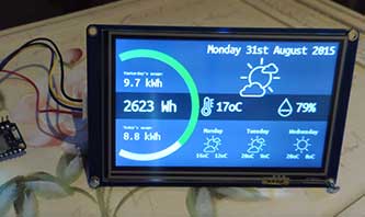
But feel free to get creative with the graphics as you like. The display I’m suggesting is extremely versatile, easy to program, and has exceptional performance. With a bit of patience, you can customize the graphics to your liking the touch screen thermostat.. In these two figures, just a couple of examples.
And so, let’s get started…!!!
Required Materials (hardware and software)
Preamble: Creating this thermostat is a bit challenging, not overly complicated, but of course, a minimum skill level in building electronic circuits and basic electronics is necessary. Nothing too laborious, just the ability to solder some components.
For the rest, it involves using some programs. Perhaps the most complex among them is Kicad, but if you don’t need to modify the printed circuit board, you can easily send the Gerber file, which I am attaching, for production and skip the Kicad and schematic section altogether.
So, let’s get to what you need
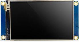
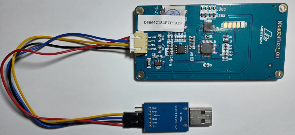
- Nextion Touch Screen. There are many sizes and resolutions available; you can find them here. I opted for the NX4024T032, which is the 3.2″ version, as seen in the first photo above, as I managed to adapt it to a Vimar plate that I have at home. Of course, there’s nothing stopping you from choosing a smaller or larger one. They range from 2.4″ to 7.0″
- A printed circuit board that you will need to create (or have created) using the attached Gerber files, see below:
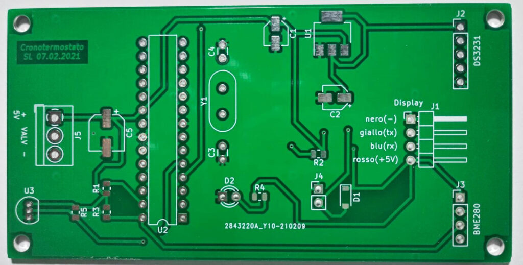
- Some electronic components to solder onto the printed circuit board, which you will find in the component list below;
- A Serial-USB converter that you can purchase for a few euros here or here. You will need it to communicate with the Nextion display and send your program to it.
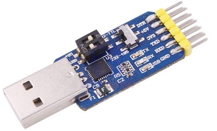
In reality, it’s not strictly necessary because you could also save the program to an SD card each time, insert it into the display’s slot, turn it on, and wait for it to load. However, that’s decidedly inconvenient. Much better is the serial communication via USB;
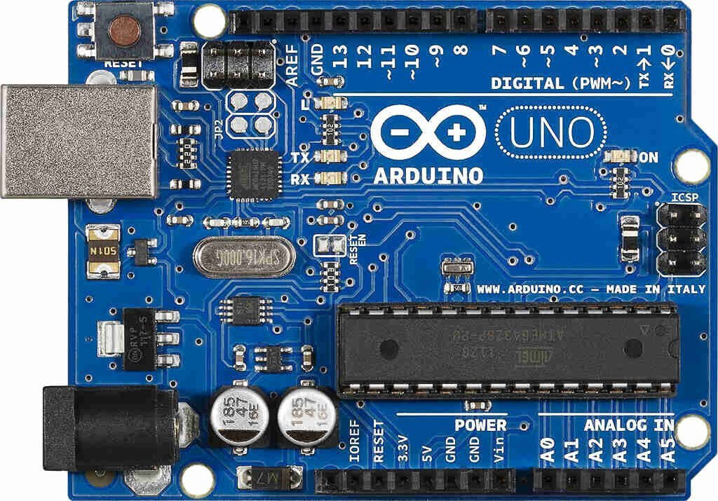
- Arduino UNO, the version with the ATMega328 on the socket, for example, this one. You will only need it to program the ATMega328, which you will then remove from Arduino to place it on your board;
- Arduino IDE, the integrated development environment for programming Arduino;
- The Nextion Editor program, a tool to customize your touch screen display;
- Kicad, free software for drawing electronic circuits, printed circuits, and the related Gerber files for production;
- The software package which includes the C program for Arduino, the program for the display, and the Kicad drawings. You can find everything in this zip file. Save the .zip file on your PC and extract its contents.
The Touch Screen
Nextion displays are very popular among hobbyists, especially those who enjoy working with Arduino. The manufacturer provides software with a graphical interface for programming the display, called Nextion Editor.
Download it from the official website and install it on your PC, then launch it.
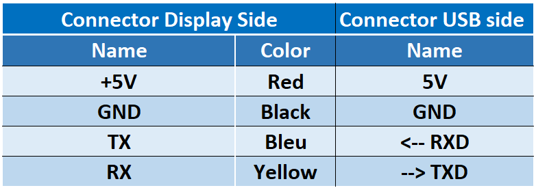
Finally, we need to upload the software, but before doing that, we have to connect the display to the USB port. Take your serial-USB converter and connect it to the Nextion display using the provided cable, following the schematic below
Now go back to the Nextion Editor program
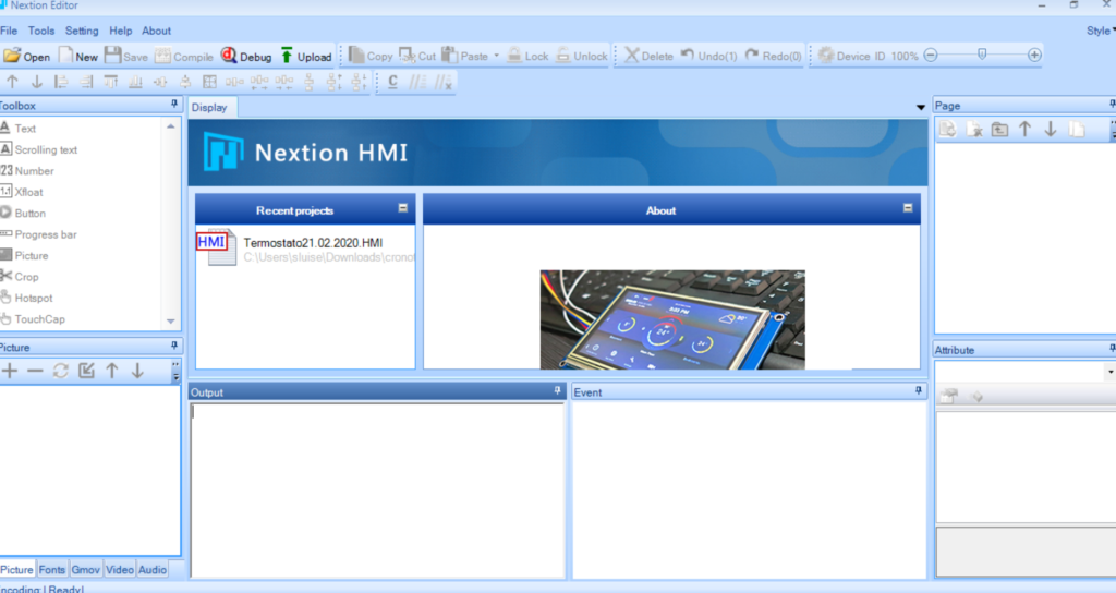
Select File -> Open and open the file Termostato21.02.2020.HMI located in the Nextion_HMI folder among the files you downloaded earlier.
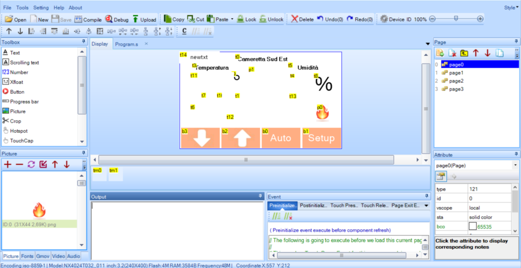
Now press the Upload button. But first, if you want, you can modify the texts by writing them in your preferred language and customize your DIY touch screen thermostat.
In the Upload to Nextion Device window that opens, select the Com port corresponding to the Serial-USB converter, in the image below it’s COM4, but in your case, it might be different.
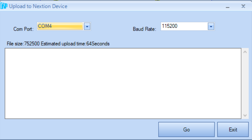
Press Go and wait for the upload to finish.
The display will show the graphics you saw in the Nextion Editor. Obviously, the temperature, pressure data, etc., are missing as they will be transmitted by the microcontroller that we will connect.
The control electronics of the touch screen thermostat
So, we have a display, now we need something to send it the data to display.
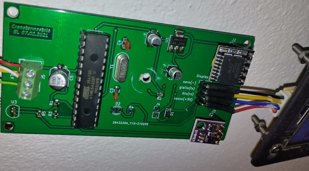
In the file package you downloaded, in the kicad folder, you have the electrical schematic of the control electronics. Open the file Cronotermostato.sch with Kicad, and you will see this schematic.
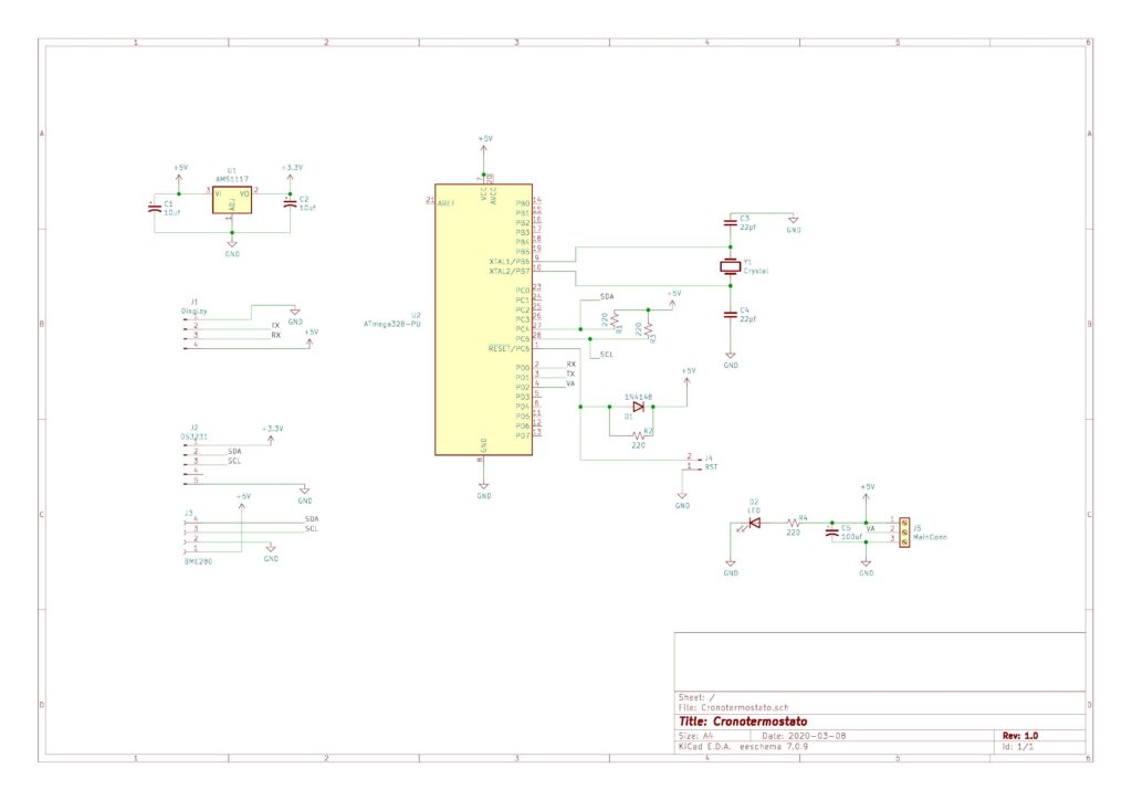
Explanation of the touch screen Thermostat Circuit
The heart of our touch screen thermostat circuit is the ATMega328 microcontroller, the same one used for Arduino.
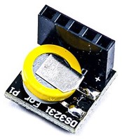
You can see it at the center of the schematic, and the surrounding electronics are truly minimal. The only other active component is the AMS1117 for converting from 5V to 3.3V. There are also some connectors for serial interfacing with the display and the other two active elements, namely the DS3231, which is the clock
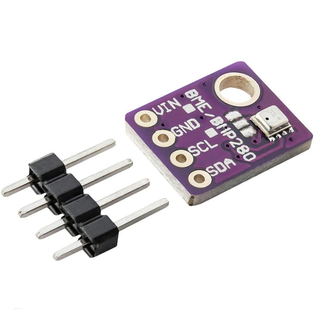
and the BME280, the sensor capable of detecting temperature, pressure, and humidity
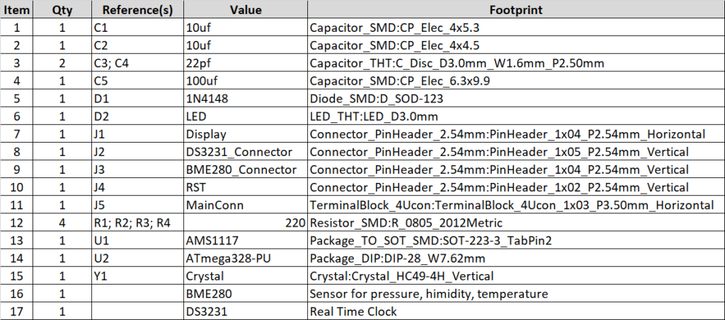
DIY Touch Screen Thermostat Components List
Assembling the DIY touch screen thermostat.
As you may have noticed from the components list, almost all of them are surface-mount. This is to reduce space since it will likely be placed inside a recessed box, which is generally quite compact.
The cost of the materials is a few euros, especially if purchased from a well-known Chinese distributor.
The slightly more complex part is creating the printed circuit board. Open the PCB file with Kicad, modify text and component placement as desired, then go to File -> Fabrication Outputs -> Gerbers and create the Gerber files. At this point, you can send the Gerber files to one of the many PCB manufacturers who will produce and ship it to your home for a modest amount.
Solder the components onto the board, and when placing the BME280 and DS3231, pay attention to the pin position and to the serial connection with the display.
The final result will be very similar to this.
THE THERMOSTAT SOFTWARE
You now need to upload the program into the microcontroller.
The best way is to place the ATmega328 in an Arduino, connect the latter to the PC, launch the Arduino IDE, and open the Nextion_Cronotermostato.ino file located in the Arduino folder with it.
Now transfer the program to Arduino, when the upload is complete, disconnect Arduino, remove the ATmega328 from the socket, and insert it into the socket on the printed circuit board.
You can power the circuit through the connector labeled MainConn with a continuous voltage of 5V.
THERMOSTAT AND TOUCH SCREEN OPERATION
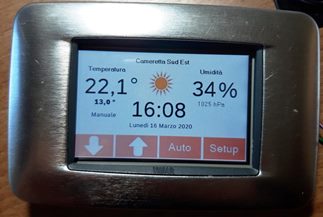
The main screen of your thermostat with a touch screen, which is also the one you return to from any submenu if you don’t touch the display for at least a minute, is as follows
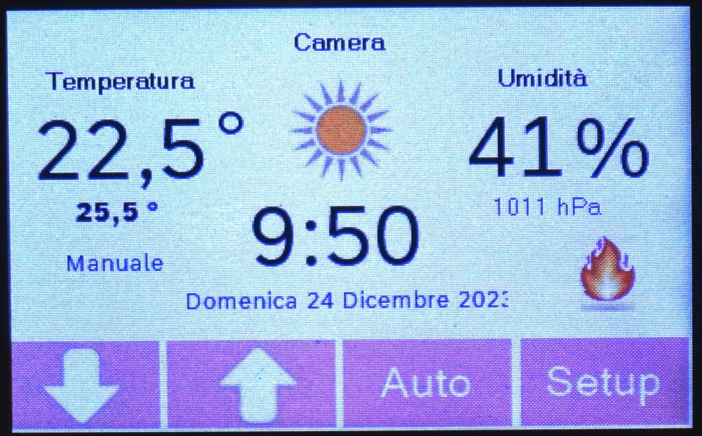
The image you see above and all the following images are photos of the display, the quality is poor, I’m sorry, but I couldn’t do better. I assure you, however, that the display quality is excellent.
On the left, prominently, you can see the room temperature (22.5°C), below it in small font is the programmed temperature (25.5°C), and even lower is the operating mode, which is Automatic (NOTE: I don’t keep it at 25.5 degrees in the house in winter; today is sunny, warm, and I deliberately increased the temperature just to turn on the flame :))
In the center, from the top, there’s the room name (Camera), the weather forecast that changes according to atmospheric pressure (increasing tendency for good weather, decreasing for bad weather), then the date and time.
On the right, from the top, there’s the relative humidity, pressure in Pascal, the ignition indicator (if the programmed temperature is higher than the current one) or off (if the programmed temperature is lower than the current one).
At the bottom, from the left, buttons to increase or decrease the temperature, they only work in manual mode. Then the button to switch between Automatic and Manual mode or vice versa. Once in manual mode, you can set the temperature using the up and down arrows seen in the photo.
The last button at the bottom right is for settings.
SETUP MENU
Pressing Setup from the main screen brings up this menu
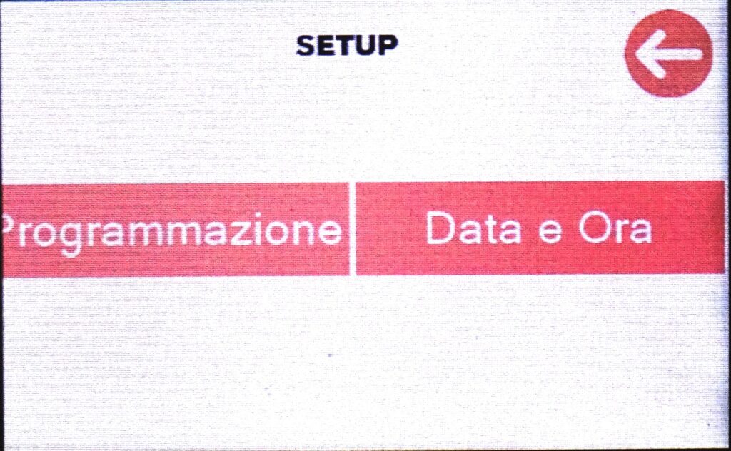
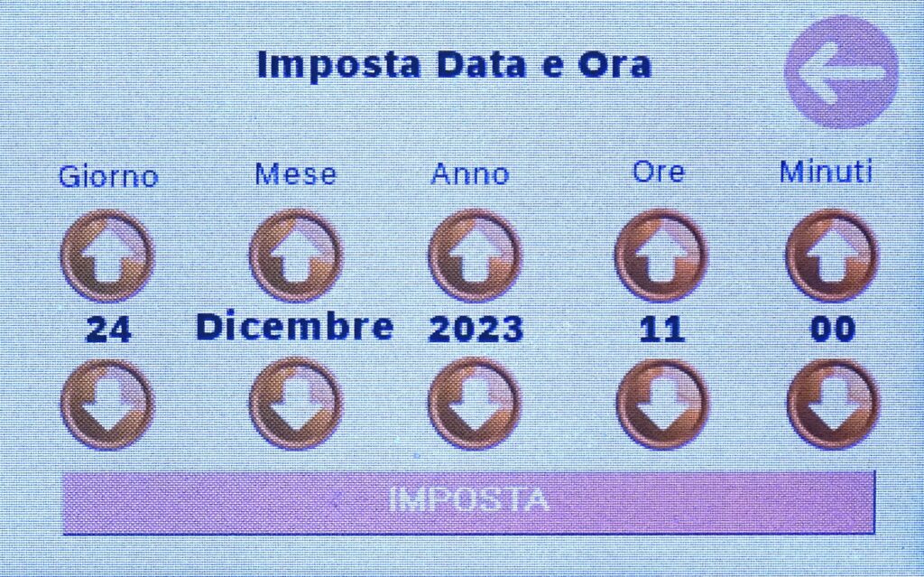
Changing Date and Time
Selecting Date and Time, you can set the current date and time
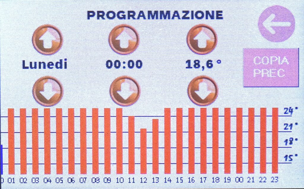
Thermostat Programming
With Programming, you can program the on and off periods and temperatures in the different daily time slots of your thermostat with a touch screen.
Last but not least, the output labeled as VALV on the printed circuit board should be connected to the solenoid valve that opens and closes the heating circuit. The voltage is 5V, and it will be appropriate, of course, to use a relay for controlling the solenoid valve.